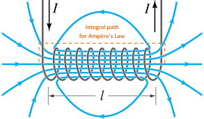
A solenoid is tightly coiled helical arrangement of a wire that maximises the Magnetic Field that goes through it’s loops when a current is flowing through it. They operate in a similar principle to Capacitor (Physics)s*, in the sense that they generate a uniform, straight field.
*See Inductor (Physics)s for the magnetic equivalent to capacitors.

Magnetic Field
Note Magnetic Field of a Solenoid
\vec{B} = \mu_{0} nI = \mu_{0} \dfrac{NI}{l}
>[!terms]- >* $\vec{B}$ = [Magnetic Field](Magnetic%20Field.md) (in $\text{T}$) >* $n$ = Turns per unit length ($\text{1/m}$) >* $N$ = Total turns of wire ($\text{unitless}$) >* $l$ = Length of solenoid (in $\text{m}$) >* $I$ = [Current](Current.md) flowing through solenoid (in $\text{A}$)
Relation to a Magnet
Derivation (using Ampère’s Law)
Assume we have a solenoid with a current flowing through each of the loops inside it, with loops and a total length of . Also assume the magnetic field is only flowing between the solenoid (due to superposition)#todo
Using Ampère’s Law:
We know in the amperian loop, certain sections (in red) are perpendicular to the magnetic field, so (i.e. does not contribute).
We have only two sections of the loop parallel to the field, but in one side (outside the solenoid), , so:
The total current, , flowing through the amperian loop is given by the number of loops. Because through each loop, the current flowing is the same, and not divided up:
Combining the two:
If we define to be the ratio of number of wire loops to the length of the solenoid, we get:
Which gives our formula